Introduction
The purpose of this document is to look at dehumidification performances in a constant volume system, with specific reference to the Trane engineering newsletter ‘It may take more than you think to dehumidify with constant-volume systems’ volume 29-4. These performances will be simulated in TAS Systems to show the software’s capability of modelling such systems. The newsletter referenced looks at how constant volume systems often provide difficulties in dehumidification of zones and how different strategies can get the best performance out of the system. It can be found at the link below.
A basic constant volume system will be made up of an air handler serving a single thermal zone. This provides the zone with a mixture of outside and recirculated air that has been adjusted to a required temperature. This temperature is decided by a thermostat within the zone that compares the zone temperature to the set point. The supply air temperature is changed until the sensible capacity of the coil is sufficient to cool the zone to the set point.
Often designers of these systems will size the cooling coils based on the peak sensible load. This load is when it is hottest outside, i.e. the hottest day of the year. However, the latent load on the cooling coil peaks when the outside dew point is the highest. This can mean, in some cases, that the air handler may not have enough capacity to cool the zone, and in part sensible-load conditions it will neglect to reduce the humidity of the zone sufficiently.
At peak sensible cooling, the coil cools the air to the required temperature whilst indirectly removing the latent heat from the air. At part-load conditions this becomes a problem. In order to reduce the cooling the temperature of the cooling coil is raised. This means that there will be less condensate produced over the coil and the humidity of the zone is often too high.
Each of the system arrangements, will be analysed at peak sensible load as well as peak latent load. This will show how at peak sensible load, the cooling coil temperature is increased slightly so that the sensible loads are met. This then means that less latent cooling is done, often resulting in an unsatisfactory humidity level in the zone.
It is worth noting that the results from Trane and TAS are somewhat different. This can be subject to different building models and sizes as well as operation gains and climate. The TAS example is taken to be a small classroom in Australia. This is hotter than the example that Trane uses in America. Also the Trane design condition for sensible load there is no present latent load. This means that, for example, the supply-air tempering model operates as a simple CV system. In the TAS climate however, the system is designed to remove this humidity from the system, hence the higher cooling loads of the systems. The latent load is also higher at the latent design for the TAS simulation than in the Trane data used.
Basic CV System
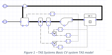
The basic constant volume system used is a simple one that was modelled in TAS systems. Any dehumidification in this system is a by-product of the sensible cooling done by the cooling coil to reduce the air temperature of the zone. Figure 1 below shows the model configuration.
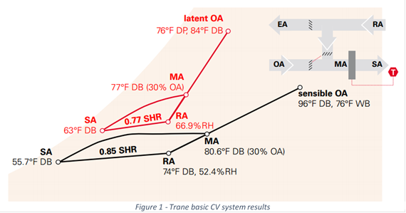
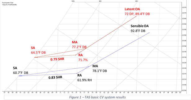
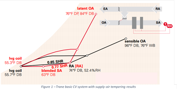
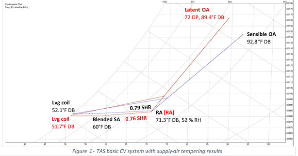
The results from Trane as well as those from the TAS simulation tell a similar story. The dehumidification at the peak sensible load relative to the peak latent load is much better. Figure 3 shows that when sensible heating is at part-load conditions the relative humidity of the zone is at 71.7%. As stated in the Trane newsletter, ASHRAE recommends that 60% RH should be the maximum. This system therefore needs to be revised in order to deliver adequate operating conditions.
Figures 2 and 3 show the Trane and TAS systems results respectively.
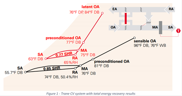
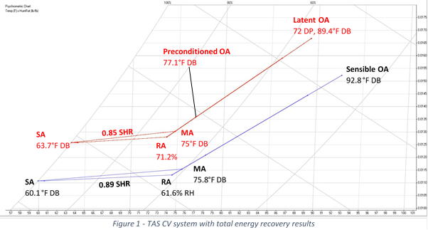
Total Energy Recovery
A passive total energy recovery wheel can be used to provide improved dehumidification. This preconditions the outside air and reduces the cooling capacity required by the coil. Latent and sensible heat are both removed from the outdoor air. This, in turn reduces the relative humidity of the zone whilst also saving on operating energy.
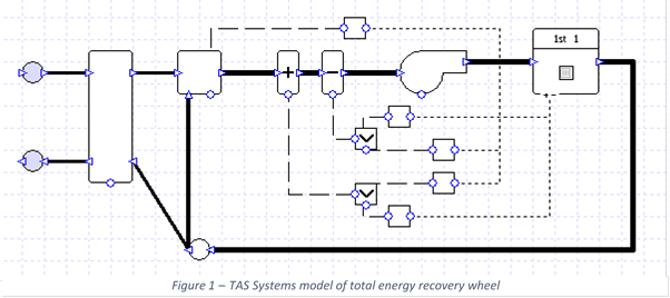
Below, figure 4 shows how the total energy recovery wheel is modelled in TAS systems with a normal heat exchanger.
Figures 5 and 6 show the Trane and TAS results of the simulations carried out. Both show a marginal improvement in performance from the basic control volume system, however this still does not meet the ASHRAE requirement – a maximum relative humidity of 60%. Further dehumidification is not possible unless the mixed-air humidity ratio is reduced to less than the return air. This cannot be done without the implementation of another cooling coil. There is also a reduction in the energy required to cool the systems. This will be shown later.
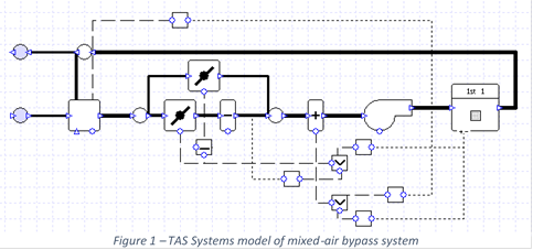
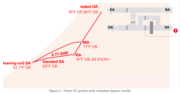
Mixed Air Bypass
Mixed-air bypass utilizes dampers to increase indirect dehumidification for the constant volume air handler. This mixes cold, dry air leaving the cooling coil with warm, moist air that is a mixture of return air and outdoor air. This improves the performance of indirect dehumidification. There is a small trade off as more ducting is required, increasing the initial installed cost.
Below, figure 7 shows the TAS model of a mixed-air bypass system. This includes dampers to direct the flow of the air to bypass the cooling coil when a latent load exists, allowing increased dehumidification to be done on a smaller amount of air.
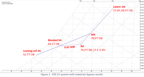
Figures 8 and 9 show the Psychrometric results for the mixed-air bypass system as found by Trane and TAS. In the case of this system, air will only bypass the cooling coil when there is a latent load present. For this reason the sensible load values can be found in figures 2 and 3 for the Trane and TAS examples respectively.
This system has the best performance results as seen so far. It is the first layout technique that, with the TAS climate and building, reduces the humidity to below the 60% ASHRAE established threshold. However, this is done under the peak latent load. All mixed air passes through the cooling coil under sensible load, meaning that no further dehumidification is done relative to the original basic CV example.
Seperate Paths
One form of direct dehumidification is the separate path technique. This involves treating the outside air and return air streams separately before mixing them. This separate treating can make more latent cooling removable occur that the previously discussed models.
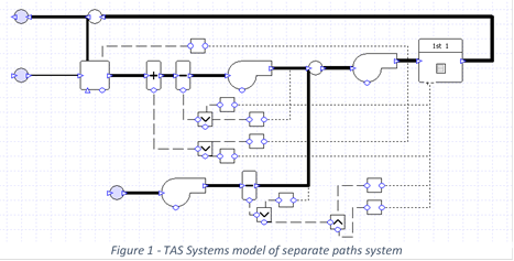
Below, figure 10 shows the TAS model of the separate path layout. The lower cooling coil is not only controlled by temperature, but also by relative humidity. This stream is then mixed with the return air stream that is used in the previous models.
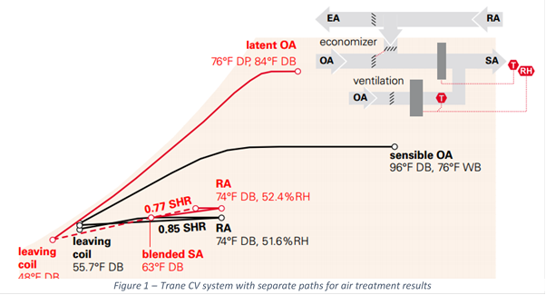
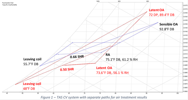
Figures 11 and 12 show the Psychrometric results for the separate air method. The performance between the Trane and the TAS models differ due to some limiting factors. In the TAS example the main point stopping the further dehumidification of the air is the leaving coil temperatures. These mean that the upon
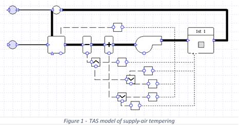
Supply Air Tempering
Supply-air tempering adopts the method of using a cooling coil directly followed by a heating device in series. This means that the cool is free to cool as much as is required to remove enough latent heat from the air. Directly after the coil, this air is often too cool to be placed directly into the zone so it is heated up to the desired temperature. The result is air at the desired temperature with a named relative humidity. The cooling coil is controlled not only by temperature, as has previously the case, but by a humidistat as well. Enough cooling is done to meet either the sensible load, or if a reduction in humidity is required, cooling to reduce the latent heat in the air.
Below, figure 13 shows TAS systems layout of the supply air tempering method. The only change between this and the original basic CV model is the use of a humidistat on the cooling coil. The heating coil then automatically reheats the air up to the required temperature to meet the zone temperature as set by the thermostat.
Figures 14 and 15 below show the Psychrometric results for the Trane and TAS systems simulations. As can be seen, supply-air tempering means that the relative humidity in the zone can always be controlled to the desired point. This is true for both peak sensible load and peak latent load. When designing the CV system, the size of the cooling coil needs to be sized to meet the loads both the sensible and design condition. This is automatically calculated in TAS systems.
The results show that both Trane and TAS expect a dramatic increase in dehumidification performance.
Comparison of Dehumidification Enhancements
Below are comparisons of the dehumidification and cooling loads of the Trane and TAS simulations. Figure
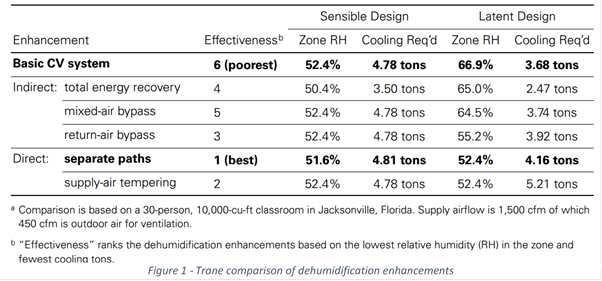
| Sensible Design | Latent Design | ||||
|---|---|---|---|---|---|
| Enhancement | Effectiveness | Zone RH | Cooling Req. | Zone RH | Cooling Req. |
| Basic CV System | 5 | 61.9% | 0.92 tons | 71.7% | 0.7 tons |
| Total energy recovery | 3 | 61.6% | 0.77 tons | 71.2% | 0.58 tons |
| Mixed-air bypass | 4 | 61.9% | 0.92 tons | 57.2% | 1.06 tons |
| Seperate paths | 2 | 60.2% | 1.70 tons | 56.1% | 1.84 tons |
| Supply air tempering | 1 | 52.0% | 1.27 tons | 52.0% | 1.31 tons |
Looking at the separate paths model in figure 17, more cooling is required at the latent load relative to the sensible load. In the Trane example this is not the case. This is due to the greater latent load present in the TAS climate model used. This is shown by the lower sensible heat ratio present when comparing figures 11 and 12. This means that more cooling has to be done to remove the heat. As well as this there is a greater specific load on the coil when at the latent condition. This is shown in the Psychrometric charts previously seen.
From the TAS simulations it can be seen that supply-air tempering is the best means of dehumidification. The best form will differ with varying climates that experience different sensible and latent loads.]]>